Home Batteries
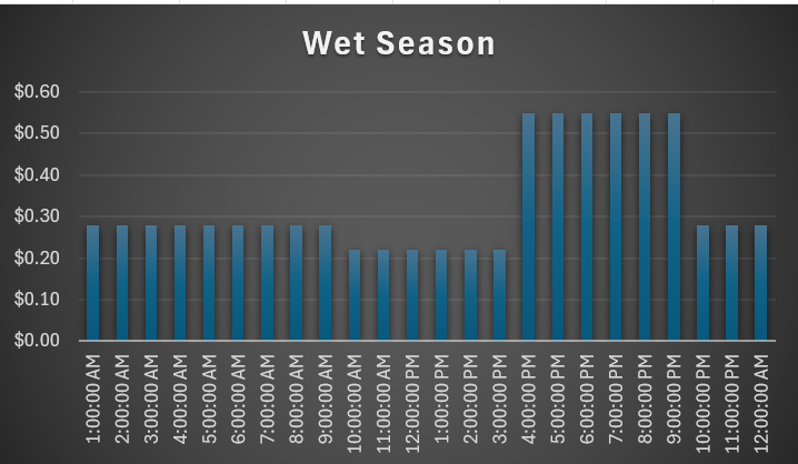
Why now might be the best time to buy a home battery
Simplifying the New Solar Installation Standard (AS/NZS 5033:2021) for You
Simplifying the New Solar Installation Standard (AS/NZS 5033:2021) for You
Simplifying the New Solar Installation Standard (AS/NZS 5033:2021) for You
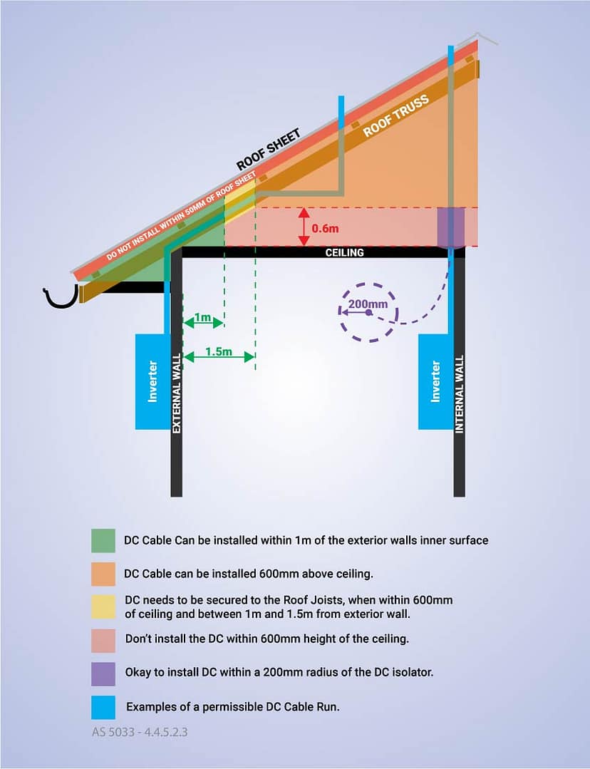
Simplifying the New Solar Installation Standard (AS/NZS 5033:2021) for You
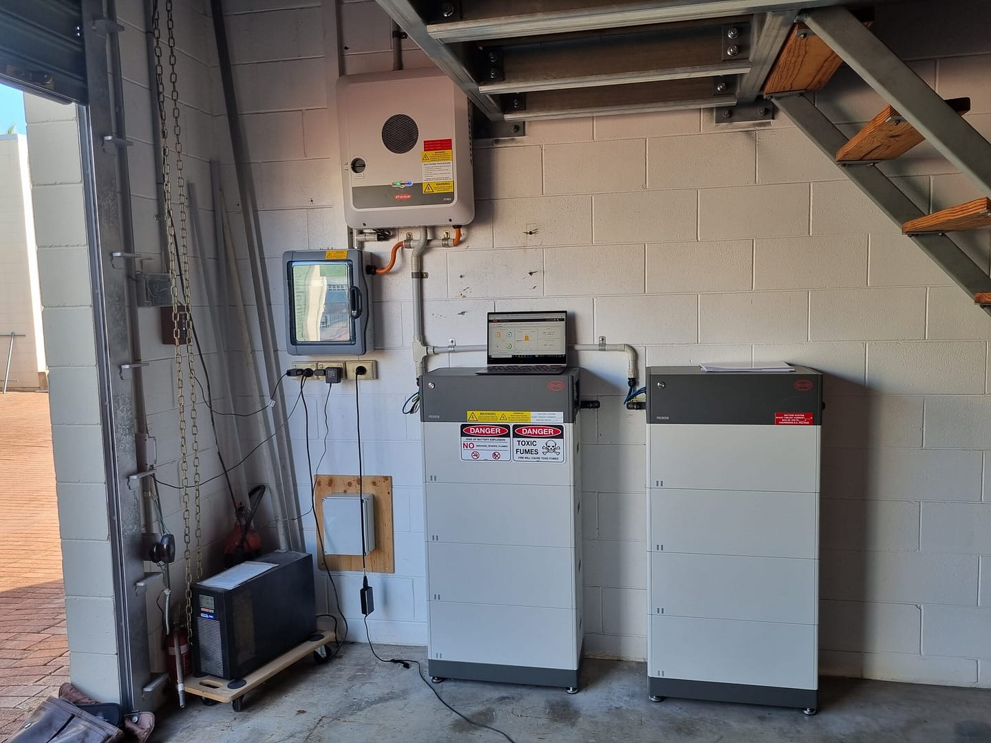
THE DIFFERENCE BETWEEN AN AC & DC COUPLED SOLAR BATTERY

The world’s largest compressed air energy storage facility has reached full operation in underground salt caverns in the eastern Chinese province […]

Australia is keen to build key components of the solar supply chain, and a new study says a plan to make solar wafers could be competitive. The post […]

Tesla has unveiled its newest energy product and the buzzy new item is, in fact, a rooftop solar panel, launched at a tumultuous moment for the EV […]

Plans to develop a hybrid solar and battery facility with up to eight hours of storage duration and 10 electric vehicle charging bays given federal […]